My adventurers with automating a standing desk and controlling it via an API.
Sitting is the new smoking, and standing desks are all the rage. But they are prohibitively costly, and thus I never paid them much attention.
Recently the company I work for, introduced a WFH plan, where they gave each employee a handsome sum so that they could up their WFH game. I also saw a standing desk at one of my friend’s places and decided its the right time to get one.
One of my friends was using a desk called FlowDesk from a company called FlowLyf. After trying it out, I liked it. I went with the Flowdesk 2 model, as it was big and spacious.

During the initial days, there was a lot of sitting, standing and a lot of button pressing involved. But soon, I found myself in a sitting position all day. Turns out, a mere motorized standing desk cannot compete with epic laziness. So, I went ahead and did what any respectable engineer would do – Automating my standing desk.
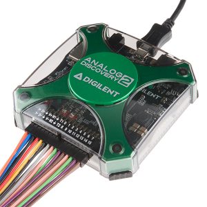
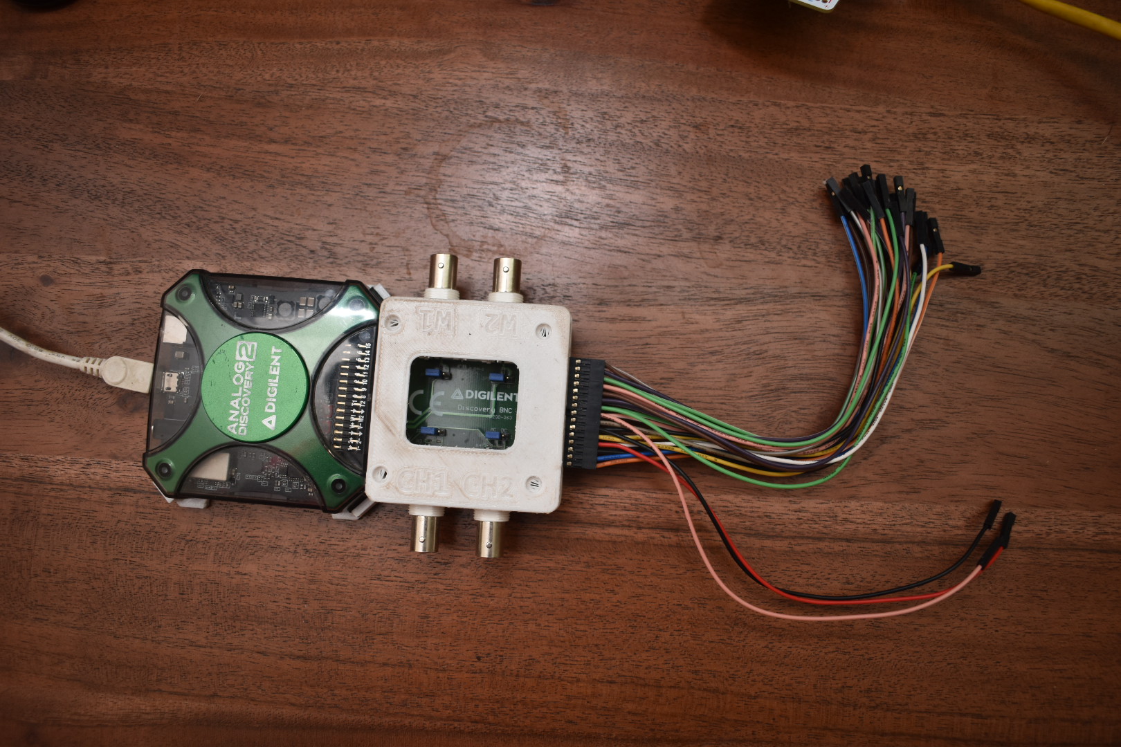
Now, I am not a seasoned electronics engineer. I am a computer engineer with a bit of electronics knowledge. But there is one thing that I do have – a love of buying things. And so I happen to have Analogue Discovery 2 – A logic analyzer.
Inspecting the hardware
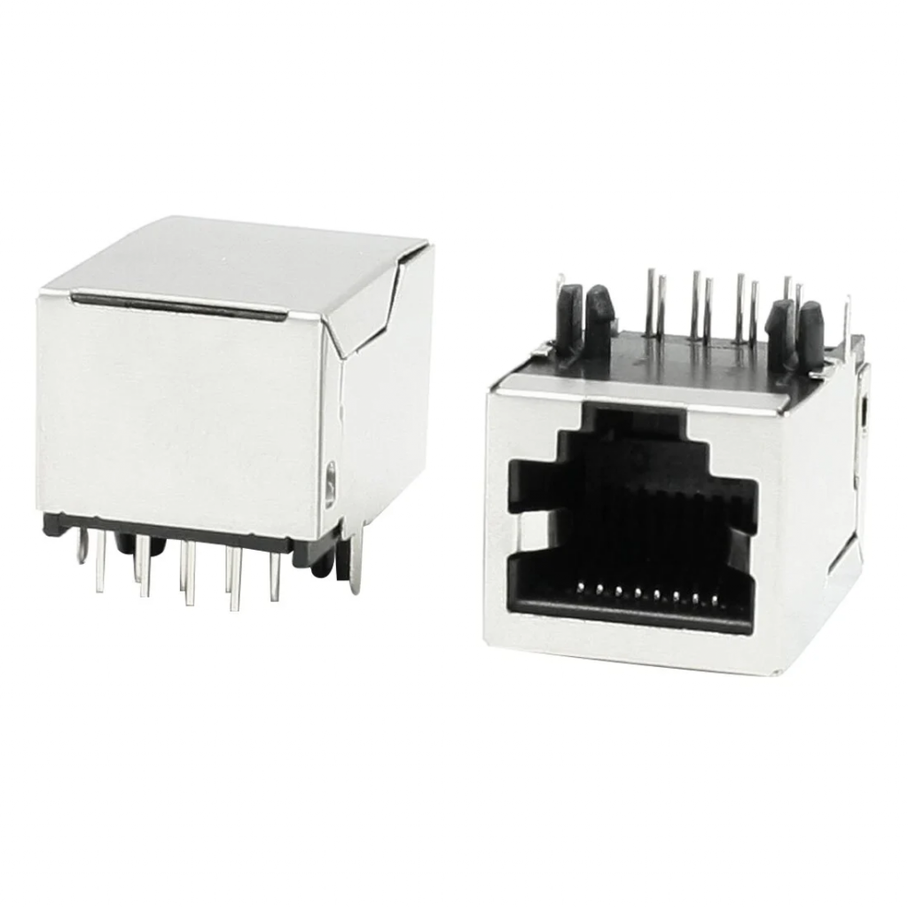
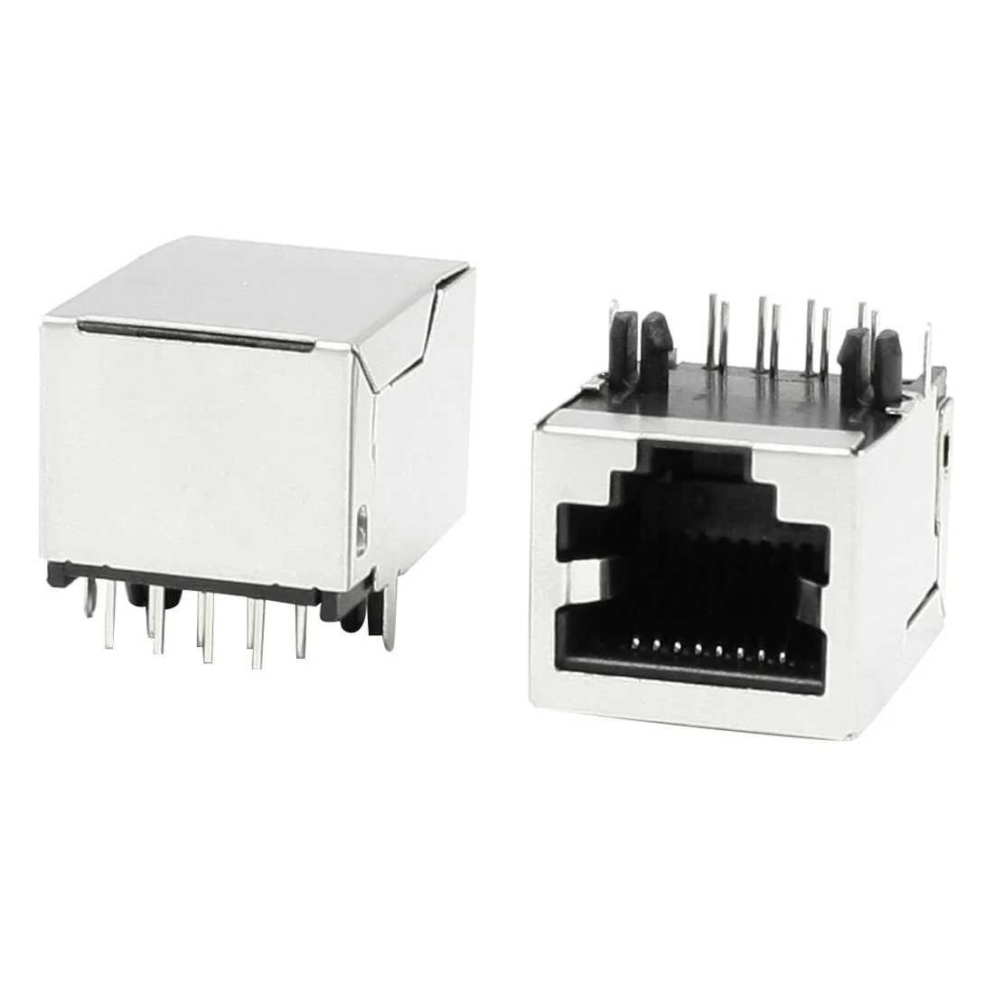
The desk itself has two linear actuators controlled by a central control box. The user interface is a panel with a segment-based display and a few buttons ( UP, DOWN, memory button, and position buttons ). This panel is connected to the control box via a cat5 cable ( RJ45 Connector ).
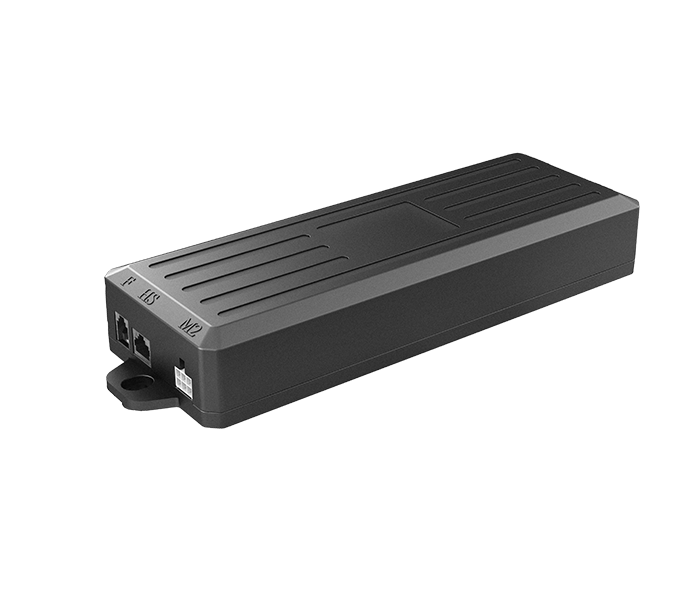
Two motor controller 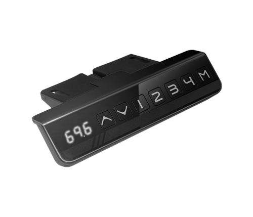
control panel
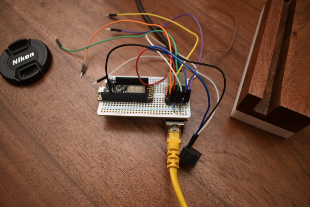
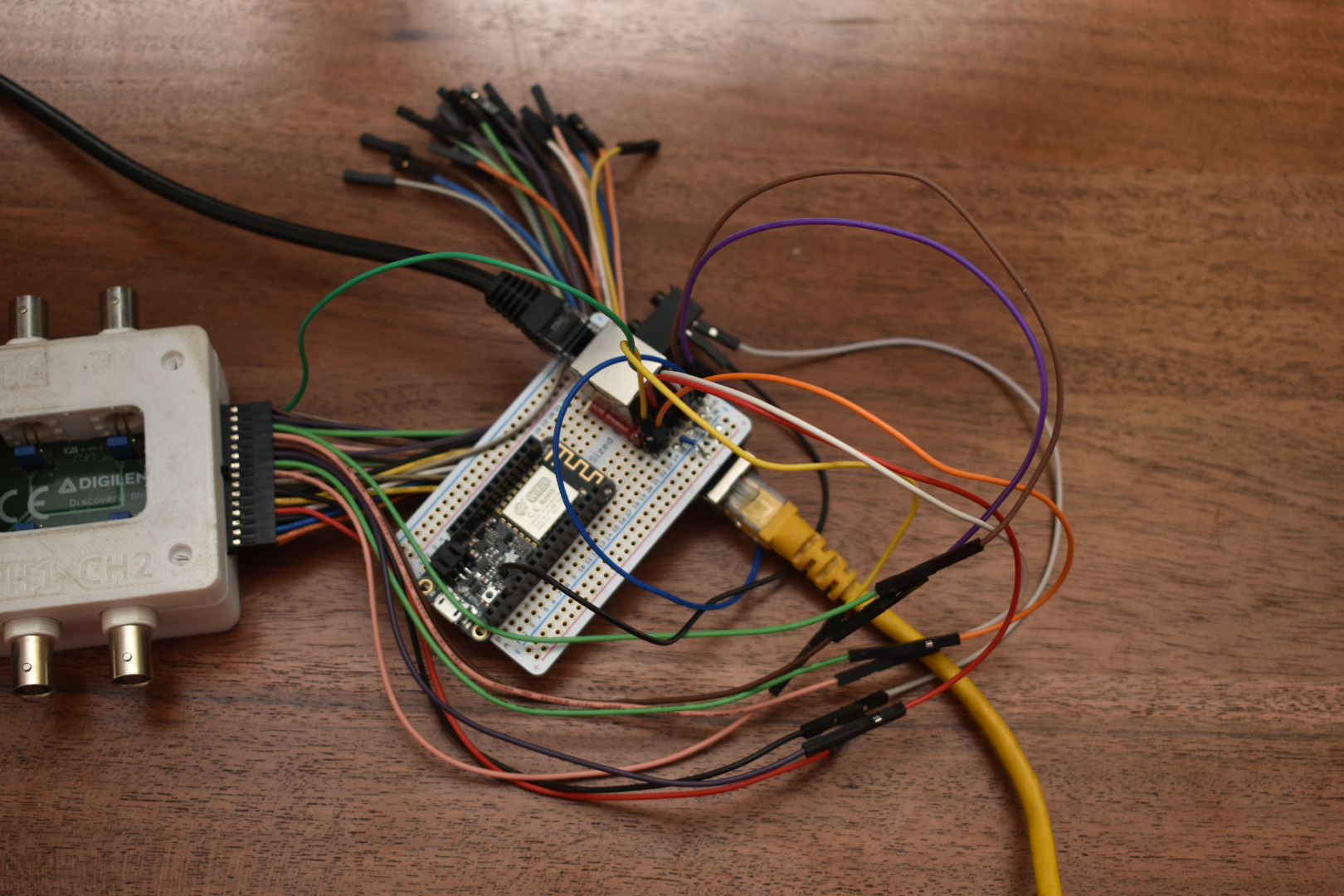
I wanted to spy on the communication between the desk control panel and the controller. So, I made a sort of passthrough for the cable, via two RJ45 ports. a Sparkfun RJ45 Breakout board was used for this. I also used a breadboard for initial prototyping which I later replaced with Adafruit breadboard PCB(before posting the article).


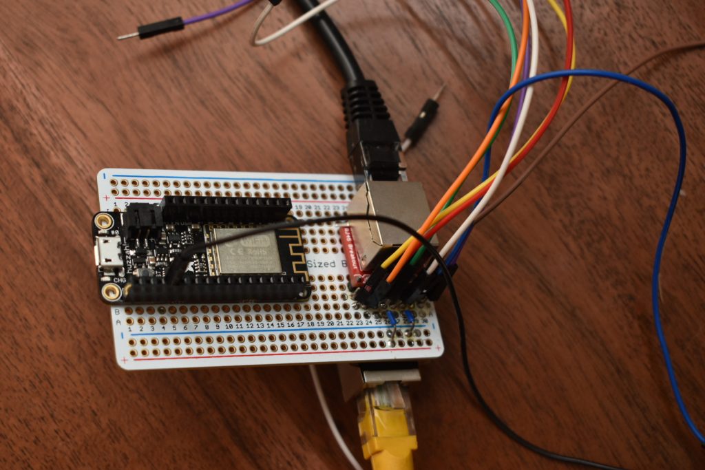
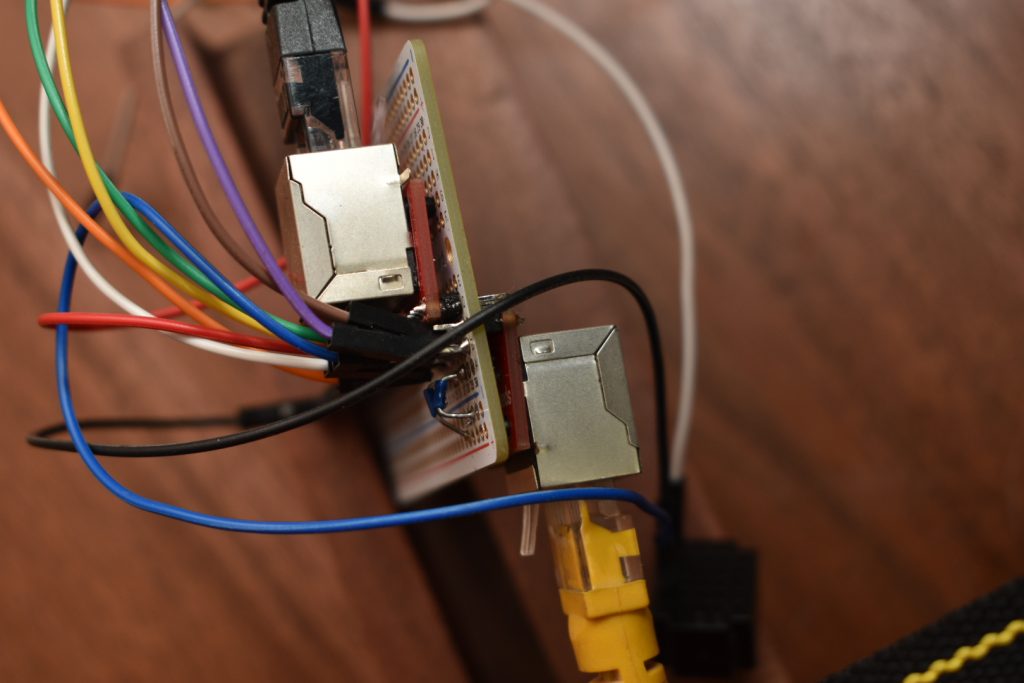
You can see the passthrough here 


Identifying the pins
The first step would be to identify the GND and VCC pins. This desk has a 5v USB charger built into the control panel. The easiest part is finding the VCC pin by touching the negative terminal to the ground area of the USB connector. And then looking for a pin with either a 5v or a 12v non-changing voltage.
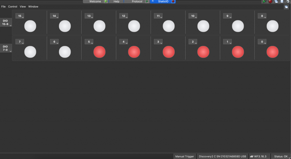
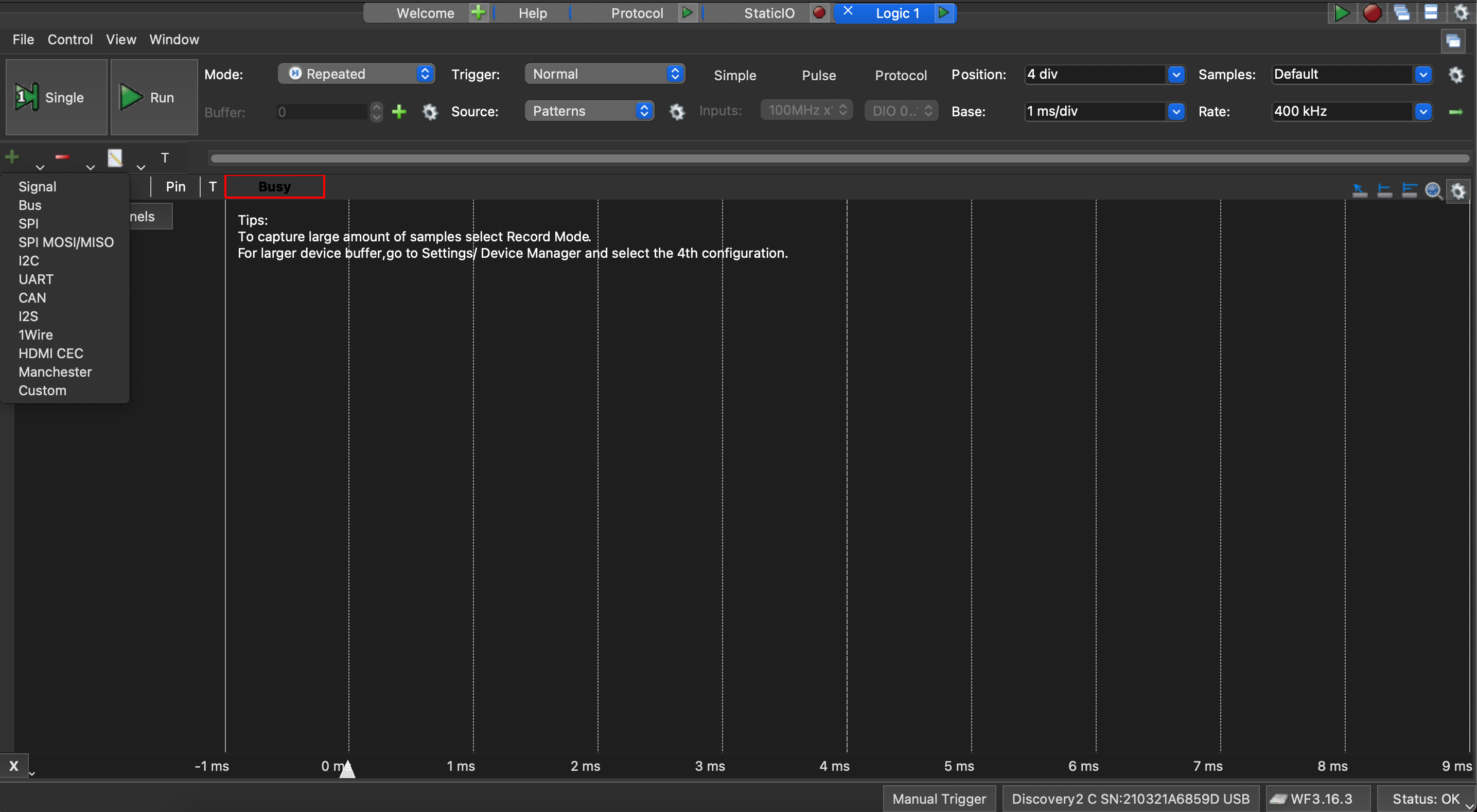
After the identification of GND and VCC pins, the next step would be to find if there is any kind of data communication ( SPI/UART/I2C ), etc on any of these pins. This one was pretty simple. I hooked all the pins ( except VCC and GND ) to data pins on my logic analyzer and then observed the static IO( the software I used is Waveforms, and comes with the Analogue Discovery 2 ).
The pins where there is constant flicker ( i.e a mix of highs and lows ) are the data pins. Be sure to hook the ground from the desk to your logic analyzer ground so the GND is common.
Next, I pressed all the buttons one by one and observed the static IO. On pressing the memory buttons, we always get a combination of pins to go low. As we have only limited GPIO lines, any extra buttons are mapped to activation of simultaneous GPIO signals.
The next thing I wanted to know was the current height of the table on the control panel. This was possible since the display updated with the correct height when the table up/down/memory position buttons were pressed.
I also knew that there was some data communication happening on a specific pin ( remember the flickering light on one of the pins )? Turns out, it’s the signal coming from the table’s central controller to the remote control panel unit.
I again fired up my logic analyzer and looked at the signal in the logic pane. I started with UART because it’s the most common protocol for a small amount of data. Also, I had a hunch that it might be UART as I could not see any clock lines ( blinking on a regular static frequency in the static IO panel ) – but again, this was a hunch.
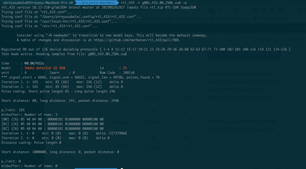
And voila, it was indeed a UART signal, with 8-bit packet 1 start, 1 stop bit, no parity, running at 9600bps.

Waveforms Logic analyzer screen 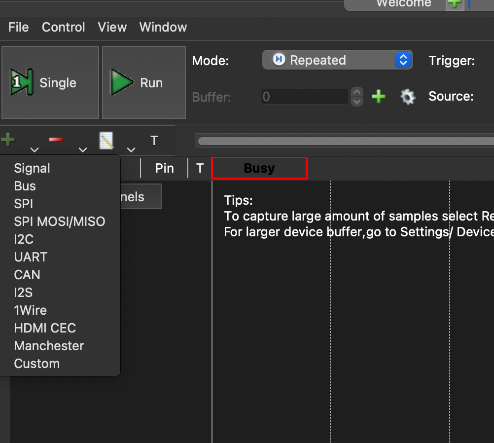
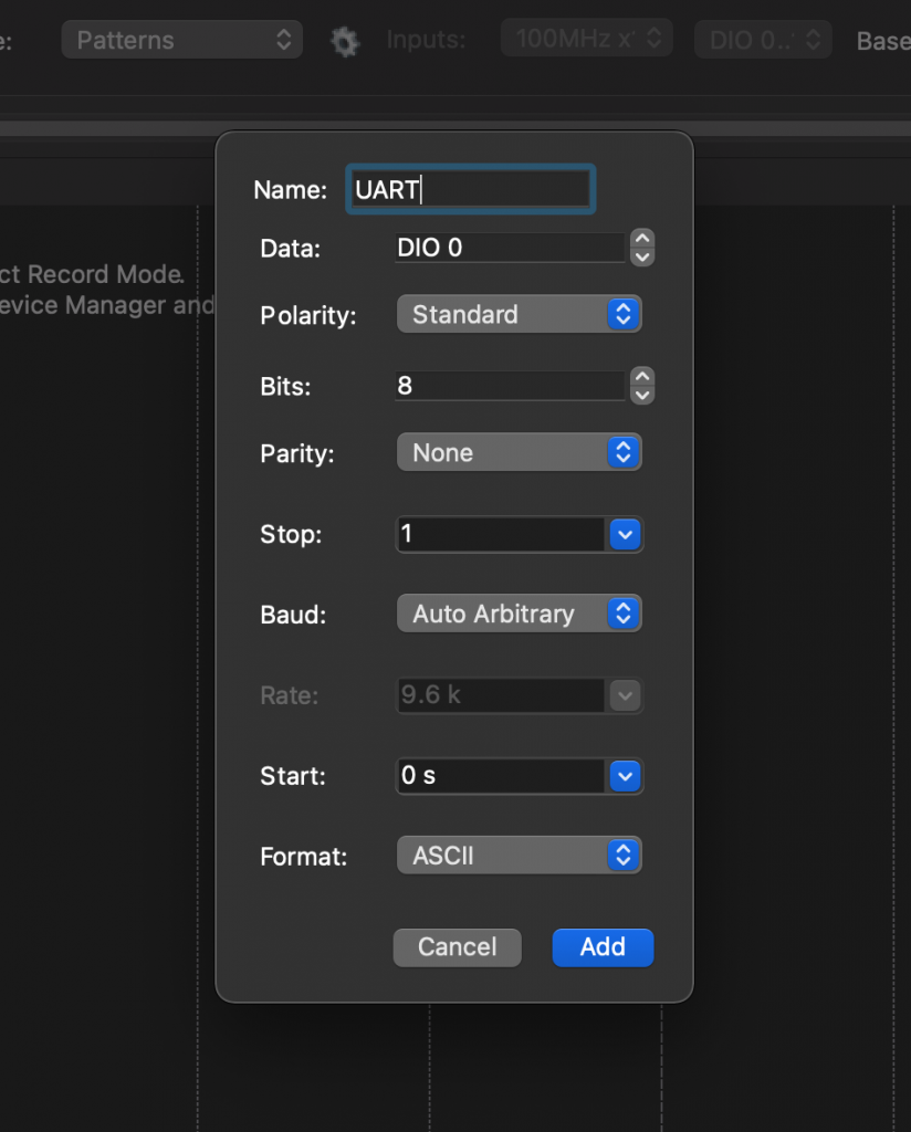
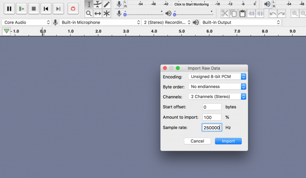
The default settings I started with 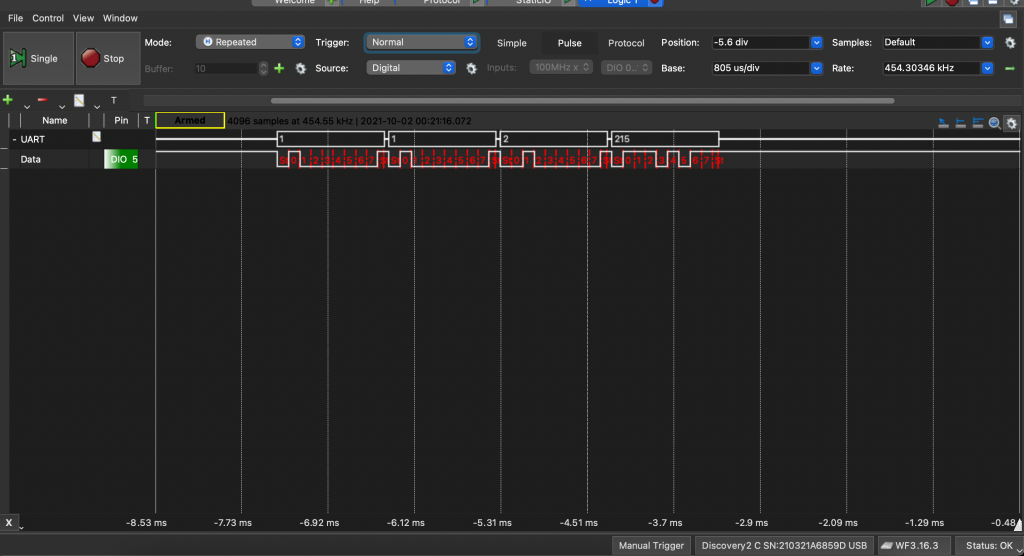
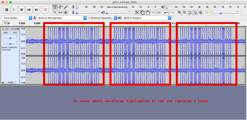
The UART signal in all its glory


Decoding the data
Now comes the hardest part, actually decoding the data. While decoding any data, I always start from repeating patterns, and on close inspection of the RX section above( i will focus on the RX section for now, as I am interested in reading the current height ) – I found that one specific pattern is repeating as illustrated in the scrtionb below.
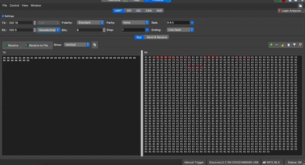
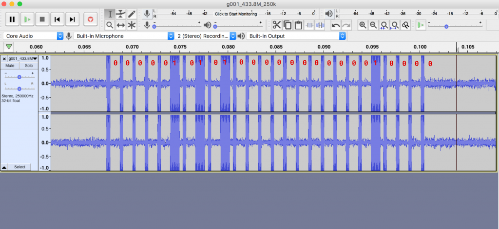
A look at the above screen shows that the value 01 01 02 E3 is repeating. So let’s focus on this value.
This is a 4-byte value, and that the first two bytes are always repeating ( even when I change the height of the desk, it’s the last two bytes that change ). When seen in decimal, it converts to 2 227.
While I was reading these values, the number on the control panel read 73.9 ( inches ). So the above value, in encoded in suck a way that it converts to 73.9.
While reading up on transferring/storing Integer/float values, I came across an article that mentioned little-endian/big-endian encoding, and in the article, it was mentioned that with big-endian, the last byte is always significant/larger.
The values I had looked like a Big Endian encoding, so I used https://www.scadacore.com/tools/programming-calculators/online-hex-converter/ to quickly decode this HEX string into a unit16 string.
On scrolling down, towards the bottom side of the site, we can see this section
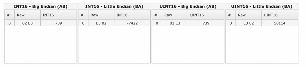
This confirms that it’s indeed Big Endian encoding, and thus we have decoded the value coming from the desk’s main controller.
The automation
Now, that I have semi-reversed the protocol ( i still don’t know what the other data line does, mostly communication from the control panel to the controller – but I don’t know yet what data is being transmitted ). I could now start with actually automating it so that we can achieve our initial goal – a programmable standing desk.
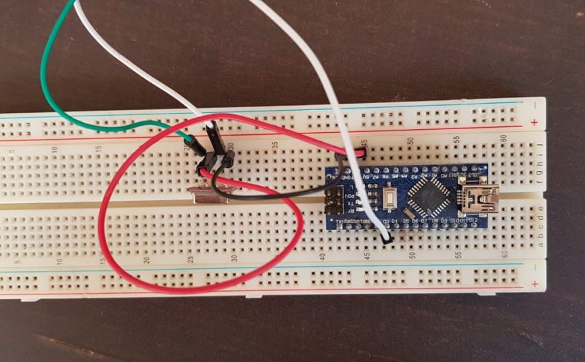
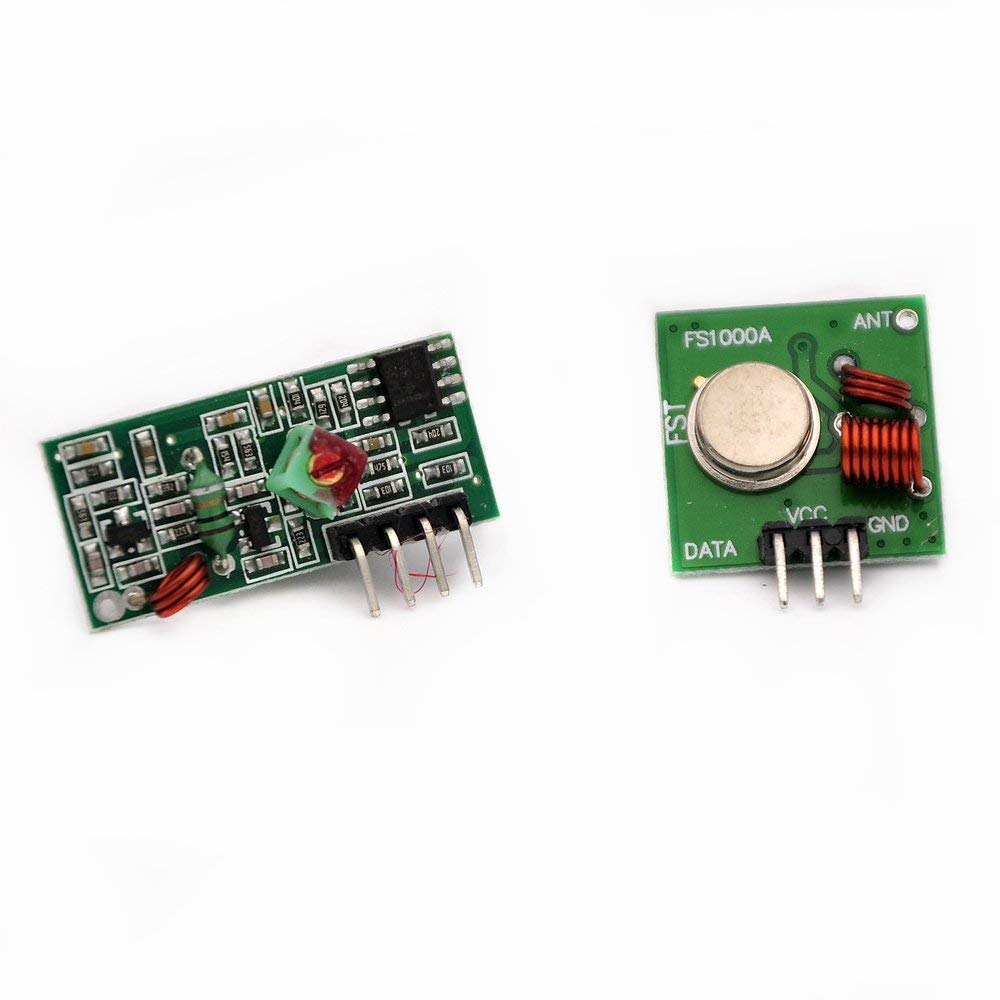
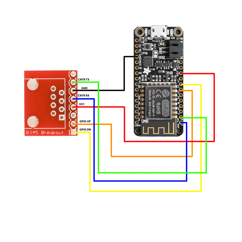
I had an esp8266 based dev board laying around, so I decided to use it. It has enough GPIOs there is loads of example code for esp8266.
Please note that as per my measurements, the high signal on the GPIO is about 5v, but esp8266 officially is only rated for 3.3v. So, i should have used a level shifter, but I have used 5v on esp8266 GPIOs before – and it does work ( at most ill fry a board – those are cheap enough, and I didn’t want to wait for the level shifter to arrive ). So, I went ahead with directly hooking it to ESP8266 GPIOs.
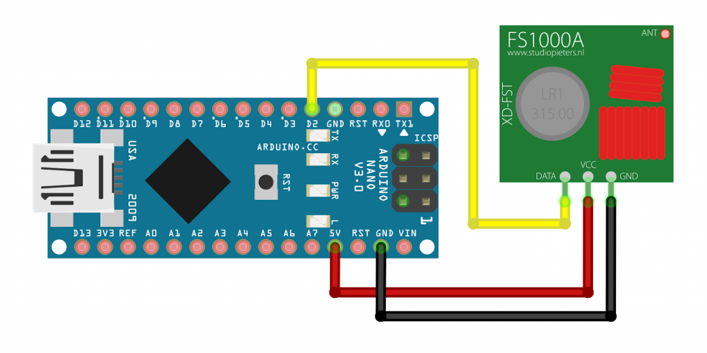
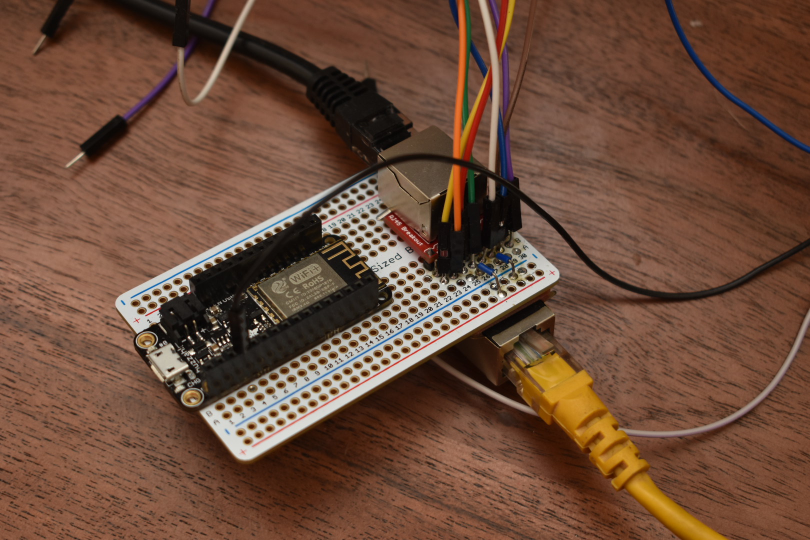
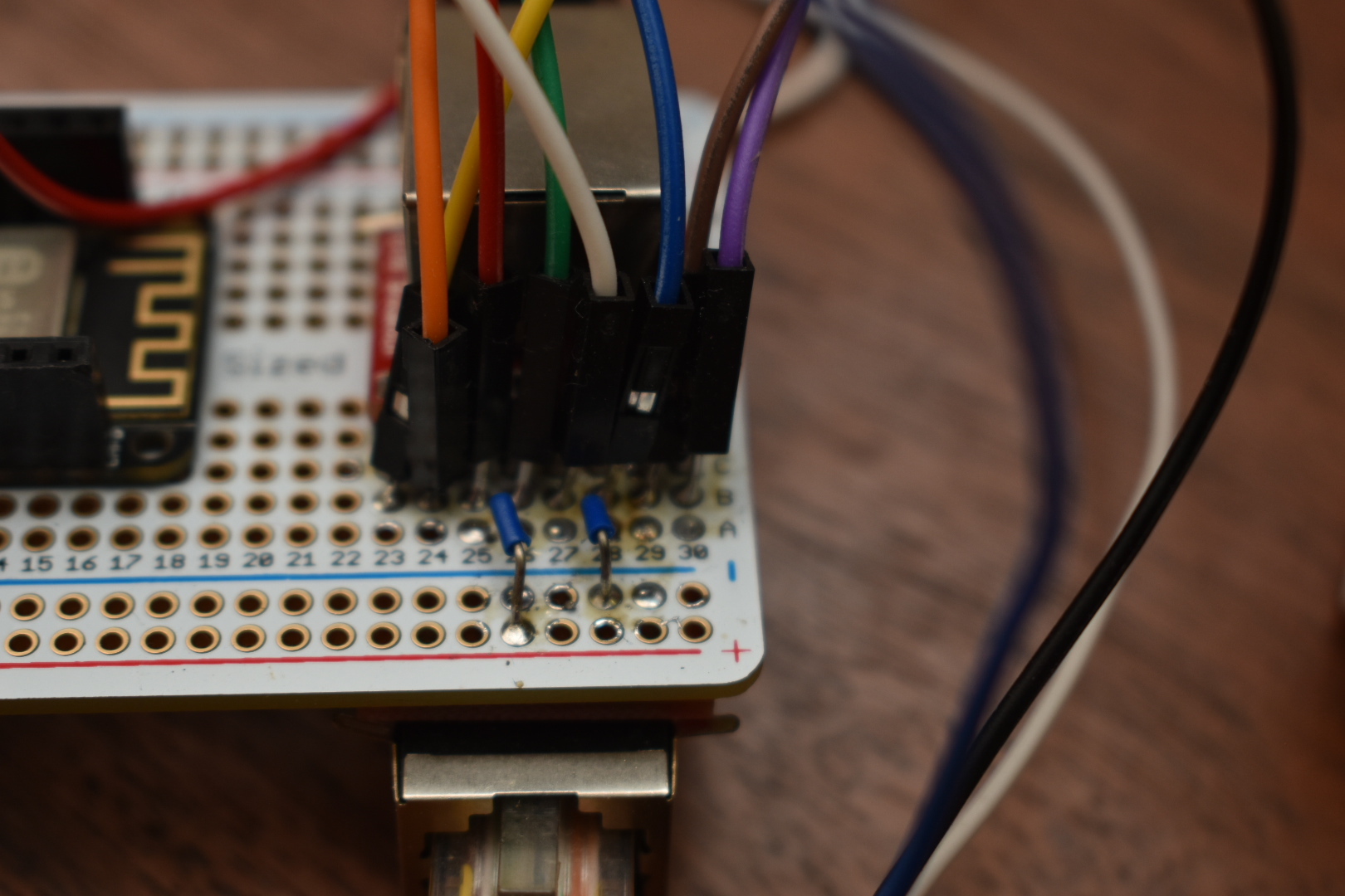
I used an Adafruit Huzzah Feather ESP8266 board. you can use any that you like. Just make sure to use the correct pins in the Arduino sketch. I connected the pins as shown below.
I do hate Arduino IDE though, it’s mediocre at the best ( have been spoiled by great IDE’s for my front-end work ). So I decided to use PlatformIO ( with VS Studio Code ). I am also attaching the Arduino version for you Arduino junkies out there.
#include <ESP8266WiFi.h>
#include <WiFiClient.h>
#include <ESP8266WebServer.h>
#include <ESP8266mDNS.h>
#include <Arduino.h>
#include <ESP8266WiFi.h>
#include <SoftwareSerial.h>

#define MAX_MILLIS_TO_WAIT 1000  //or whatever
#define DOWNPIN   12
#define UPPIN   13
#define UPOP  1
#define DNOP  2
#define NOOP  0
#define ACTIVATE LOW
#define DEACTIVATE HIGH
#define DESKMOVEDDURINGREAD 9


SoftwareSerial deskSerial(5,4);

#ifndef STASSID
#define STASSID "Your SSID"
#define STAPSK  "Your pass"
#endif

int currentOperation = NOOP;
unsigned long starttime;
const char* ssid = STASSID;
const char* password = STAPSK;
unsigned long value;
int RFin_bytes[4]; // The message 4 bytes long
int currentHeight = 0;
int requestedHeight = 0;
int heightMultiplier = 1;

//Initialize the webserver
ESP8266WebServer server(80);

const int led = LED_BUILTIN;

void handleRoot() {
  digitalWrite(led, 1);
  server.send(200, "text/plain", "hello from esp8266!\r\n");
  digitalWrite(led, 0);
}

/* This method decodes the serial data*/
int decodeSerial() {
  while ( deskSerial.available()<4 ){
        // hang in this loop until we get 4 bytes of data
  }
  if(deskSerial.available() < 4){
          // the data didn't come in - handle that problem here
        Serial.println("ERROR - Didn't get 4 bytes of data!");
  }
  else{
      for(int n=0; n<4; n++){
        RFin_bytes[n] = deskSerial.read(); // Then: Get them.
          Serial.println(RFin_bytes[n]);
      }
  }

  //Serial.println("==========");

  uint16_t myInt1 =   (RFin_bytes[2] << 8) + RFin_bytes[3]; // Convert Big Endian to Unit16
  Serial.println(myInt1);
  if(myInt1 > 1259 || myInt1 < 600){
    decodeSerial(); // Wrong value, try again
  }
  return myInt1;
}


/* This method stops moving and sets the requested height to current height */
void stopMoving(void) {
  digitalWrite(DOWNPIN,DEACTIVATE);
  digitalWrite(UPPIN,DEACTIVATE);
  currentHeight = requestedHeight;
  currentOperation = NOOP;
}

void setHeight(int height) {

  int operation = 0;
  requestedHeight = height;
  if(currentHeight > requestedHeight) {
    operation = DNOP;
  };
  if(currentHeight < requestedHeight) {
    operation = UPOP;
  };

  if(currentHeight == requestedHeight) {
    operation = NOOP;
  };
  switch(operation){
    case UPOP:
      digitalWrite(UPPIN,ACTIVATE);
      currentOperation = UPOP;
      Serial.println("going up");
    break;
    case DNOP:
      digitalWrite(DOWNPIN,ACTIVATE);
      currentOperation = DNOP;
      Serial.println("going down");
    break;

    case NOOP:
      currentOperation = NOOP;
      stopMoving();
      break;

    default:
      stopMoving();
    break;
  };
}


void setup(void) {
    deskSerial.begin(9600); // The controller uses 9600 bauds for serial communication
    Serial.begin(115200); // Use the in built UART for debugging
    // Disable pullups turned on by espSoftwareSerial library
    pinMode(5, INPUT);
    pinMode(led, OUTPUT);
    pinMode(DOWNPIN,OUTPUT); // Default is HIGH
    pinMode(UPPIN,OUTPUT);  // Default is high

    pinMode(led, OUTPUT);
    stopMoving(); // Make sure there is no movement on startup

    digitalWrite(led, 0);

    WiFi.mode(WIFI_STA);
    WiFi.begin(ssid, password);
    Serial.println("");

  // Wait for connection
  while (WiFi.status() != WL_CONNECTED) {
    delay(500);
    Serial.print(".");
  }
  Serial.println("");
  Serial.print("Connected to ");
  Serial.println(ssid);
  Serial.print("IP address: ");
  Serial.println(WiFi.localIP());

  if (MDNS.begin("esp8266")) {
    Serial.println("MDNS responder started");
  }


  server.on("/", handleRoot);

  server.on("/height", []() {
    char hstr[4];
    sprintf(hstr, "%d", currentHeight);
    server.send(200, "text/plain", hstr);
  });

  server.on("/abort", []() {
    stopMoving();
    server.send(200, "text/plain", "Aborted current operation. please wait for some time before sending a new command");
  });

  server.on("/setheight",[]() {
    String message;
    // Stop all ongoing operations
    if(currentOperation != NOOP) {
      // 409 is conflict status code
      server.send(409, "text/plain", "A height adjustment operation is goin on, please try later");
    }else{
      message = server.arg(0);
      setHeight(atoi(message.c_str()));
      server.send(200, "text/plain", message);
    }
  });

  server.begin();
  Serial.println("HTTP server started");
}


// Height should be set in bursts of x ms pulses, as it takes 4ms to read the current height

void loop(void) {

  // the decodeSerial should be only called once in the loop
  currentHeight = decodeSerial();

  // These values come in either 3-4 digits , the last one always being the fractional value
  // i.e 1206 means 120.6 while 655 means 65.5
  if(currentHeight > 999) {
    heightMultiplier = 10;
  }else{
    heightMultiplier = 1;
  }
  Serial.println("CURR/REQ");
  Serial.println(currentHeight);
  Serial.println(requestedHeight);
  Serial.println("============");

  // This number is not precise, so compare in ball park
  // Based on current height
  // we assume that in the time taken to update the current height
  // the desk has moved by DESKMOVEDDURINGREAD inches
  if(currentOperation == UPOP) {
    if(currentHeight >= requestedHeight - DESKMOVEDDURINGREAD * heightMultiplier){
      stopMoving();
    }
  }
  if(currentOperation == DNOP) {
    if(currentHeight <= requestedHeight + DESKMOVEDDURINGREAD * heightMultiplier){
      stopMoving();
    }
  }
  server.handleClient();
  MDNS.update();
}
So now, we have a webserver running on ESP8266 which can report height and when set, will move the table to the desired height.
To Automate this, any home automation platform can be used(HomeAssistant, OpenHAB etc ) . I prefer Home Assistant, as its python based, but feel free to use your favourite.
Please feel free to offer any suggestions / if you would like me to cover the home assistant automation part as well.
Have fun and happy reverse engineering!