I have a two-floor individual house and I am generally upstairs with my headphones on and the main door locked. Because of this, neither my grandparents (living downstairs) nor the visitors are able to reach me
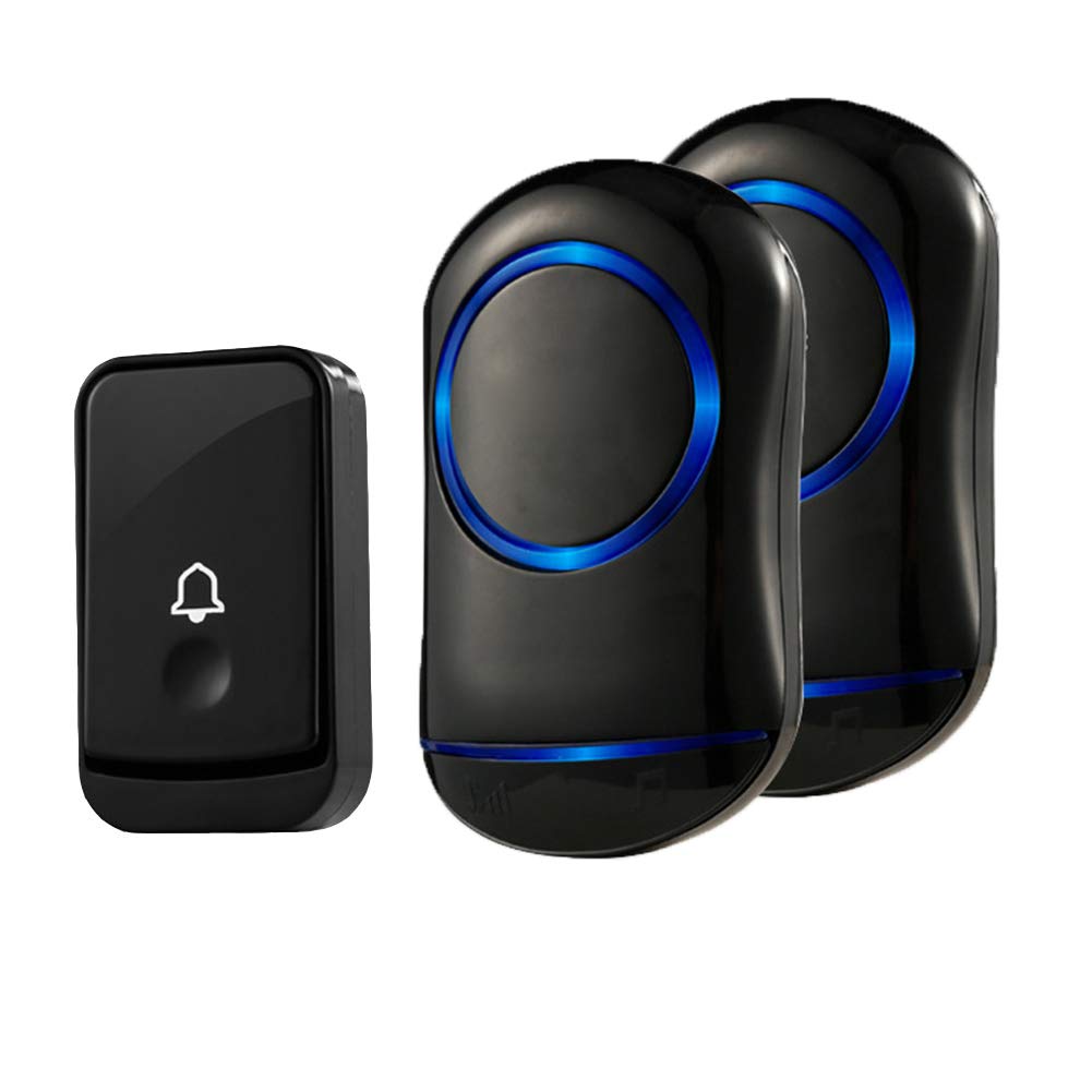
So I decided to install a doorbell and settled on the below-shown doorbell from Amazon India, the problem is, this bell has two receivers and one transmitter. This solved my visitor issue( one receiver upstairs ) but my grandparents were still not able to reach me. So I obviously did not buy a new bell and decided to reverse engineer this bell itself to make a second transmitter.
Reverse Engineering the transmission signal
The next step is to figure out which frequency band the transmitter is operating on. We can do this with an SDR and SDR software. You have various choices for the software, but I prefer either SDR# ( Windows ) or GQRX ( Linux and Mac )
https://airspy.com/download/ ( SDR#)
http://gqrx.dk/download (GQRX )
I had an SDR( Software defined radio ) lying around ( RTL-SDR v3 ), so I decided to use it. You can buy one from RadioJitter in India. These guys are official distributors for the RTL-SDR dongle.
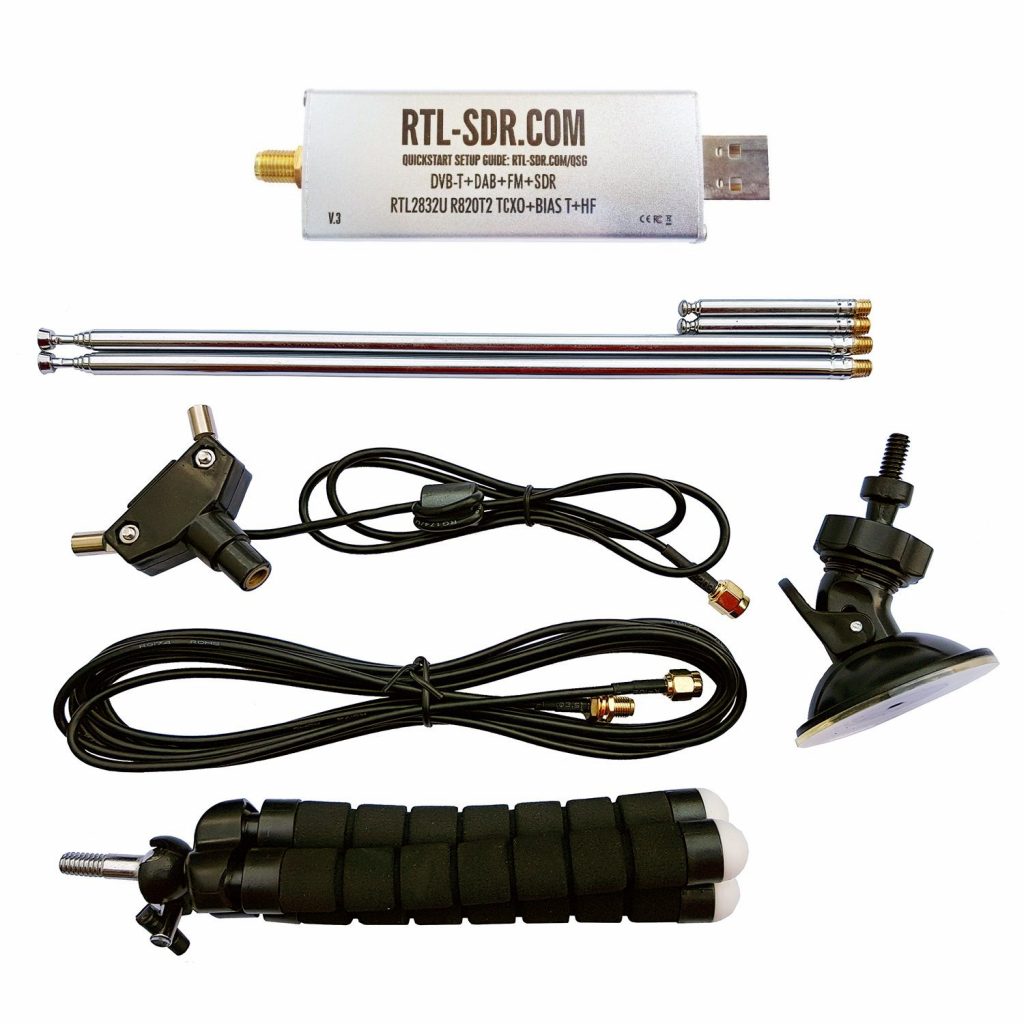
This SDR is widely supported in various software.
Before you plug in the SDR to your USB port, make sure the antenna is connected.
Doorbell Frequencies
Depending on which country you are in, there are some frequency bands allowed by the government for general purpose use. For example in India, they are 433mhz and 865-867mhz. However, if you have cheap Chinese clones, they sometimes disregard the law and might operate on different frequencies
Here are the common frequencies consumer RF equipment generally operate on:
- 315Mhz
- 433Mhz
- 915mhz
This Wikipedia article covers ism band( industrial, scientific and medical) across various countries. https://en.wikipedia.org/wiki/ISM_band
If you cannot find your signal around these frequencies ( these are actually bands, the width of the band varies, for example for 433mhz, the bandwidth is 1.7Mhz and center is 433.93Mhz which essentially means the bell can operate +- 1.72 Mhz from 433.92Mhz ( in India )
Let’s fire up GQRX( or SDR# depending on your OS ) and see which frequency our doorbell is transmitting at!
As the above video shows, the remote is transmitting at roughly 433.86Mhz. We don’t really need to know the exact frequency, as these transmitters ( and receivers ) generally work across a wide band, not just the mid-frequency of that band ( in our case, the mid-frequency for 433 MHz band is 433.92Mhz )
Now that we know the frequency of our doorbell transmitter, lets capture and analyze the signal
Capturing and Analysing the Signal
We can use various tools to capture the signal. As we already have the SDR, we will use it as the hardware. We can use either command line tools or the SDR software itself to record the signal. The signal itself is a waveform, so we can capture it as an audio and analyze it later using various tools. Both GQRX and SDR# offers functionality to capture the signal, however, I prefer command line tools.
#1 Using RTL_433
We will be using a tool called rtl_433 to capture the data. This tool offers various analysis options also and is very feature rich. You can download it from
https://github.com/merbanan/rtl_433
Once installed ( as per instructions mentioned in the link above ) open your command line and type the following command
rtl_433 -S all -f 433.83Mwhere 433.8Mhz is the frequency we figured out earlier from GQRX. -S stands for save all signals, -f specifies the frequency. This command will save the signals received by the SDR into a file in the current directory.
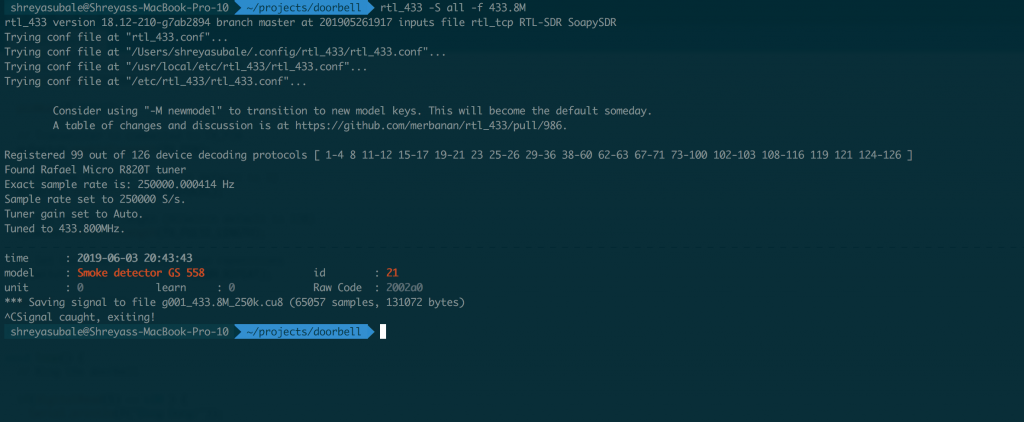
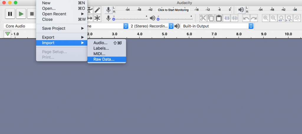
The above screenshot shows that the rtl_433 tool was able to capture and save the signal in a file called g001_433_8M_250k.cu8. Now we can analyze the waveform. We will use an open source audio editing tool called Audacity (https://sourceforge.net/projects/audacity/) for this. Install and open the tool, and then click on File -> Import -> Raw data
Then use the following settings :
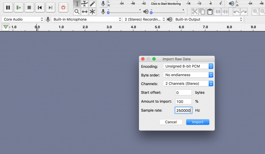
Byte Order : No endianness
channels : 2
sample rate : 250000
Now zoom in, you should be able to see the following output
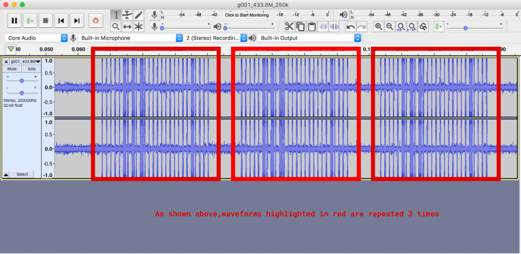
This shows the waveform that was captured. You will be able to see here that the same pattern is being repeated 3 times. Now let’s zoom in and try to make sense of one repetition of this waveform.
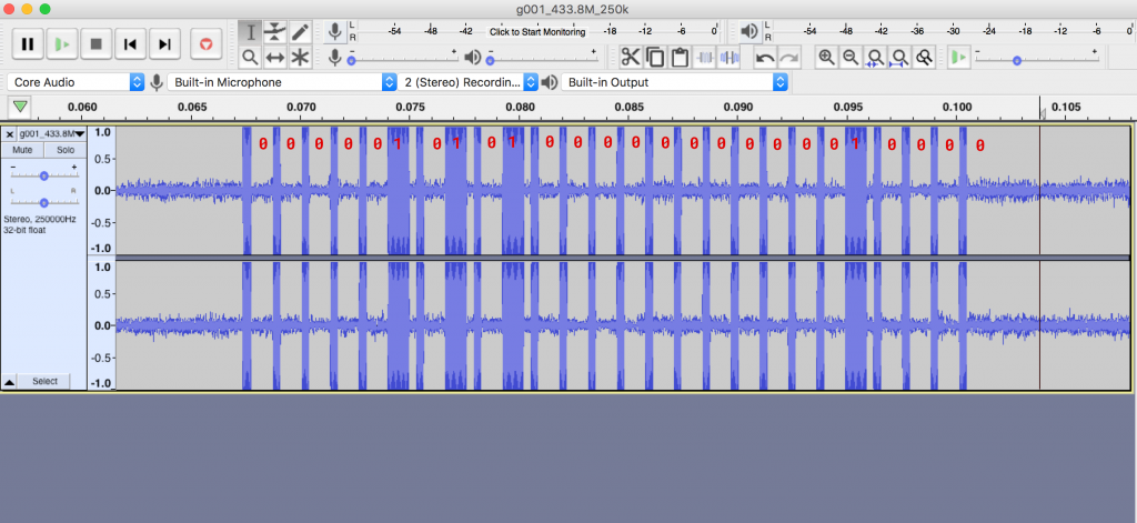
If you know digital electronics, you know that a high signal is treated as 1 and a low signal is treated as 0. Here we can see that the gap will be 0 and the thick peaks will be one. The small line diving can be thought of as a separator. That is how we get our binary representation of the waveform, which is 00000101010000000000010000
To make this step easy, let’s try doing this with rtl_433. We already saved the waveform as g001_433.8M_250k.cu8. Lets load that file in rtl_433 in analysis mode
rtl_433 -r g001_433.8M_250k.cu8 -a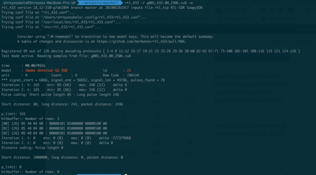
The output of the command confirms our findings with the manual waveform analysis. We also see that the length is 26bits and the long pulse length is 246. We also see that the same signal is being repeated 3 times.
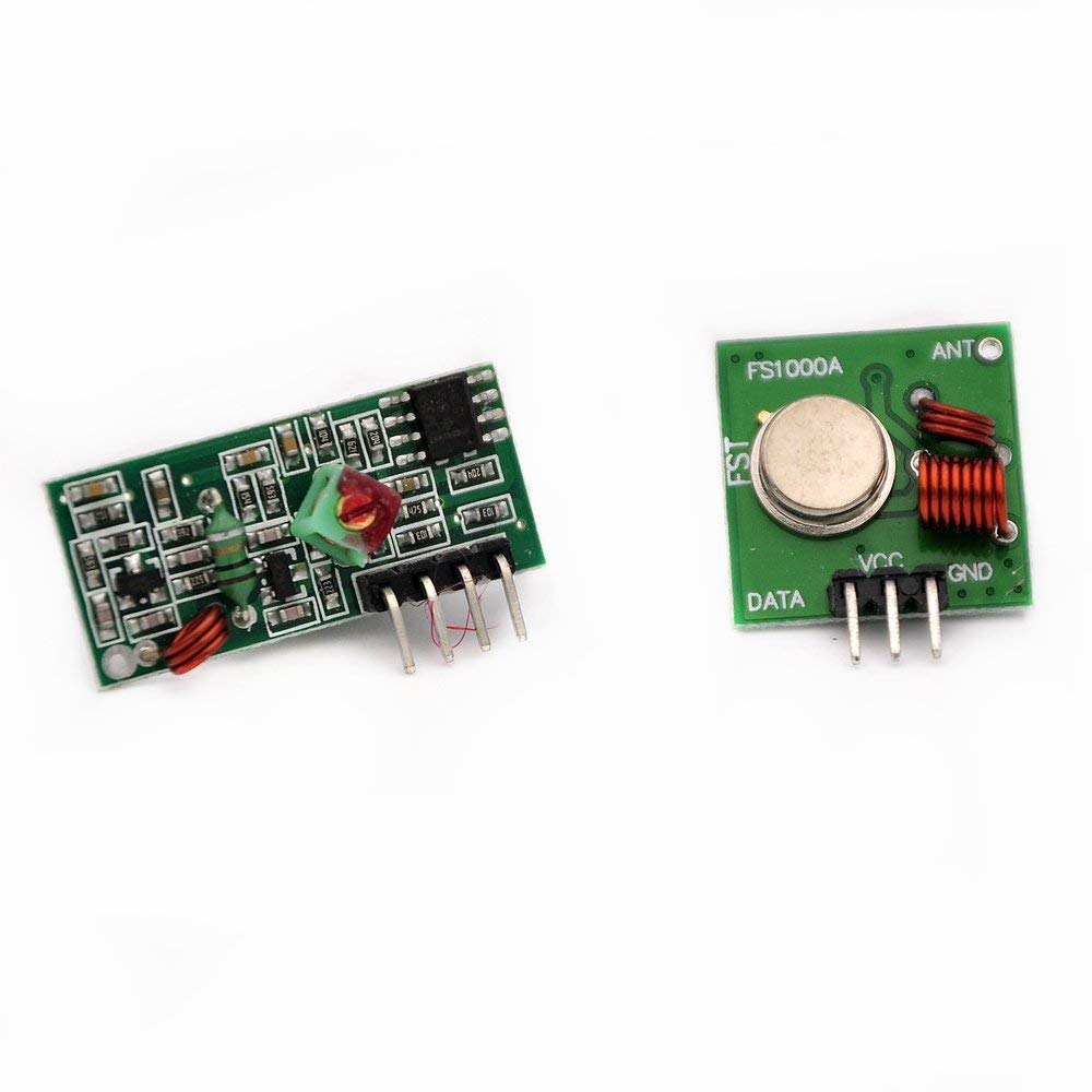
Now we have everything we need to replicate the signal. We can use various methods to transmit this signal ( we will be covering these methods in other parts of this tutorial. For now, let’s use a 433mhz transmitter module ( you can get it from Amazon ) and Arduino. The module looks like this
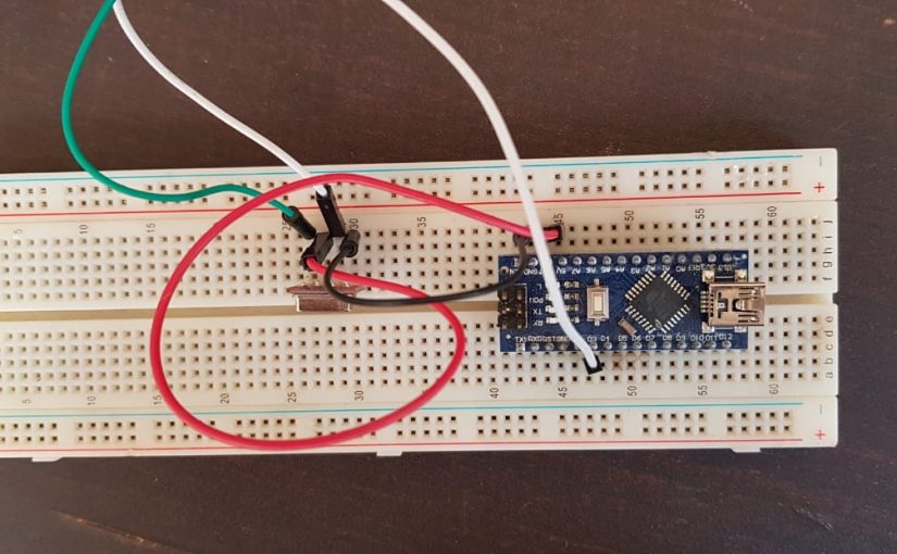
Now, let’s see how to connect the module to the arduino. We will be using an arduino nano for this.
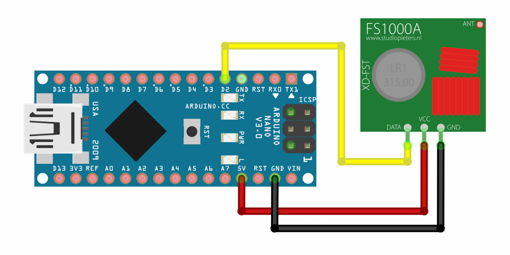
The above shows the typical wiring diagram. the data pin can be connected to any digital IO pin. In the above diagram, we are using pin D2. Make sure to power the transmitter with at least 5V ( i tried with 3.3V and found later the minimum required voltage is 3.7V as per the specs.
After prototyping on breadboard, my setup looked like this

I have used a library called RCSwitch for transmitting the radio signal. This library makes it easy to send the pulses with correct timing.you can download it from https://github.com/sui77/rc-switch. It can also be installed via the Arduino’s library manager ( just search for RCSwitch )
// by Shreyas ubale
// Jun 14, 2019

#include <RCSwitch.h>

#define TX_PIN 2
// The transmitter is connected to pin 2

// Set the numer of transmission repetitions
#define TX_NUM_REPEAT 3

// Set the pulse length
#define TX_PULSE_LENGTH 320

// The inverted signal received by the SDR using rtl_433 or
// manually decoded from the raw signal
//
// Example:
//   original: 1111100110101110011010111
//   inverted: 0000011001010001100101000
#define TX_SIGNAL "0000010101000000000001000"


RCSwitch mySwitch = RCSwitch();
void setup() {
  // Set the serial baud rate to 115200
  Serial.begin(115200);

  // Automatically sets the TX_PIN to output mode
  mySwitch.enableTransmit(TX_PIN);

  // Set the pulse length (RCSwitch default is 320)
  mySwitch.setPulseLength(TX_PULSE_LENGTH);

  // Set the numer of transmission repetitions
  mySwitch.setRepeatTransmit(TX_NUM_REPEAT);

}

void loop() {
  // Wait for 10 seconds
  Serial.println("Ringing door")bell;
  mySwitch.send(TX_SIGNAL);
  delay(10000);
}
In the code above, we are using the TX signal we decoded via rtl_433, and as we figured out from the wave pattern, this signal is being repeated 3 times, so we are emulating that in the code as well.
Now as soon as you flash this code, you should be able to hear your doorbell ring. This will continue every 10s. If you wish to stop, just unplug the arduino. You can also fire up GQRX and listen in to the frequency and verify that the signal you are transmitting matches the signal that was captured via GQRX for decoding.
In the next parts of This blog, we will be exploring various ways of transmitting the signal ( YardStick one, RpiTX on a raspberry pi ) as well as different signal decoding techniques. In the last part, ill go through the whole process of designing a simple but configurable 433mhz push button ( Like Amazon Dash ) which supports wifi as well as RF and can use IFTTT service. So stay tuned 🙂
Please feel free to ask / suggest me anything related.
Happy Hacking!